FAB Modules

all about our FAB Modules

FAB1215 – 12Volts to +/-15V, +48V Phantom Power Supply Module

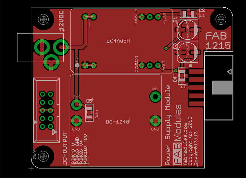
Our next board up for prorotyping is our FAB1215 Module. This is a Power Supply Module, which accepts a 12V DC input, and provides a +15V, -15V, and +48V output voltages to power your project.

The +15V and -15V will be provided by a DC-DC converter, which can provide up to 190mA per voltage rail.  The 48Volts will be provided by a FiveFish Audio DC-1248 module (12V to 48V) which can provide up to 30mA (UPDATE: Received the DC-1248 prototype boards and testing shows) 60mA maximum @ 48Volts.

Continue Reading…

FAB2110 – Input Transformer Module

Introducing – our FAB2110 Module.  This is basically our Input Transformer Module.

This FAB module will accept CAN type transformers like Jensen, Cinemag, Altran Input Transformers with it’s typical (8) pins.  CAN Transformer dimensions are 1.13″ diameter (28.7mm) with 0.15″ pitch pins.

FAB2110 Input Transformer Modules are designed to mate with our FAB2010 XLR Input Modules.  This allows you to create a complete Transformer-based Input Stage for that Mic Preamp or gear you’re building.

The FAB2010 XLR Input Modules require power (V+, 48V) for proper operation of it’s relays (controlling the -20dB Pad and Phantom Powering) and 48Volts Phantom Power. These power requirements cam be supplied via the POWER INPUT headers of the FAB2110 Input Transformer Module.  You can use a 2×5 (10-pin) Ribbon Cable to connect this POWER INPUT header to our FAB Power Supply*. Continue Reading…

FAB2010 – XLR Input Module

0 Comments
FAB Modules, FAB2000 Input Modules
Tags: , ,
Posted by: admin

The first FAB Module that will be available is a FAB2010, an XLR Input Module.

The FAB2010 has the following features:

  • PCB Mounted Neutrik XLR Female Jack
  • RFI Protection
  • Soft-Start 48Volt, Phantom Power
  • -20dB Pad
  • Logic Level (+5V) Pad and Phantom Power Control
  • Using a mixed of SMD (Surface Mount Devices) and TH (Through-Hole) components

Here’s a screenshot of the current prototype design. I hope to get this PCB design sent out for fabrication this week so I can start testing. After a successful test, I’ll provide the schematics and some application notes on this website. You will also be able to purchase PCBs if you’re adventurous to DIY assemble them (it’s easy!) or you can also purchase ready-made FAB2010 modules from our online store* (Pricing TBA). Continue Reading…

FAB Modules PCB

0 Comments
FAB Modules
Tags:
Posted by: admin

Our FABModules will come in a variety of standard sizes. They’re designed to minimize user-error when plugging the modules to each other by having the boards keyed, i.e. you can’t insert them  the wrong way.

Most FABs will have  the standard 2×5, 0.1″ pitch, Input and Output header connections. These connectors transfer all signal and voltages throughout your signal chain.

Some FABs will only have Output headers, or only Input headers… depending on the functionality.

For example, an XLR Input FAB Module will only have Output headers and no Input headers.  While an XLR Output FAB Module will only have an Input header, without an Output header.

In a few special cases, some FABs won’t have either the standard 2×5 Input or Output header. A few cases I can think of will be Switch modules, or Gain Selector modules.  In these special cases, there will be headers designed to connect these modules to other modules via jumper wires.

pcbsample


FAB Modules PinOut Diagram

0 Comments
FAB Modules, FABModules PINOUT
Tags:
Posted by: admin

All FABModules connect to each other via standard 0.1″ pitch Male/Female headers.

INPUTS will be Female 2×5, 0.1″ pitch headers.

OUTPUTS will be Male 2×5, 0.1″ pitch headers.

The 2×5 Header pin outs are as follows. Note the location of the “notch”.  The headers will be inserted/soldered on the edge of the PCB with all ODD-Numbered Pins on the top copper side, and all EVEN-Numbered Pins on the bottom copper side. See diagram below.

2x5-IDC-Pin-Numbering

Continue Reading…