
All FABModules connect to each other via standard 0.1″ pitch Male/Female headers.
INPUTS will be Female 2×5, 0.1″ pitch headers.
OUTPUTS will be Male 2×5, 0.1″ pitch headers.
The 2×5 Header pin outs are as follows. Note the location of the “notch”. The headers will be inserted/soldered on the edge of the PCB with all ODD-Numbered Pins on the top copper side, and all EVEN-Numbered Pins on the bottom copper side. See diagram below.

This is the TOP-SIDE VIEW. Note the RED Color of the PCB, as represented by Eagle CAD.
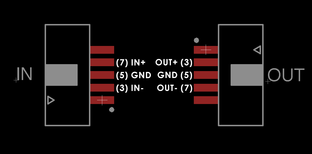
INPUT JACK, TOP SIDE PIN OUT:
- (3) IN-
- (5) GND
- (7) IN+
OUTPUT JACK, TOP SIDE PIN OUT:
- (3) OUT+
- (5) GND
- (7) OUT-
This is the BOTTOM-SIDE VIEW. Note the BLUE Color of the PCB, as represented by Eagle CAD.

INPUT JACK, BOTTOM SIDE PIN OUT:
- (2) +48V
- (4) V+
- (6) GND
- (8) V-
OUTPUT JACK, BOTTOM SIDE PIN OUT:
- (4) V-
- (6) GND
- (8) V+
- (10) +48V