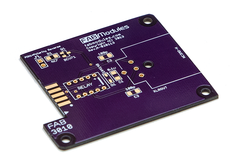


A lot happened last week as our prototype PCBs began arriving. We populated the prototype boards and verified them to be working electrically. Some boards will need a Revision B redesign for some mechanical clearances before mass production.
The following boards were tested last week, and I’m happy with the results.
FAB2010 XLR Input Module
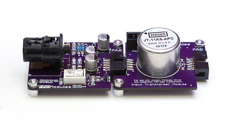
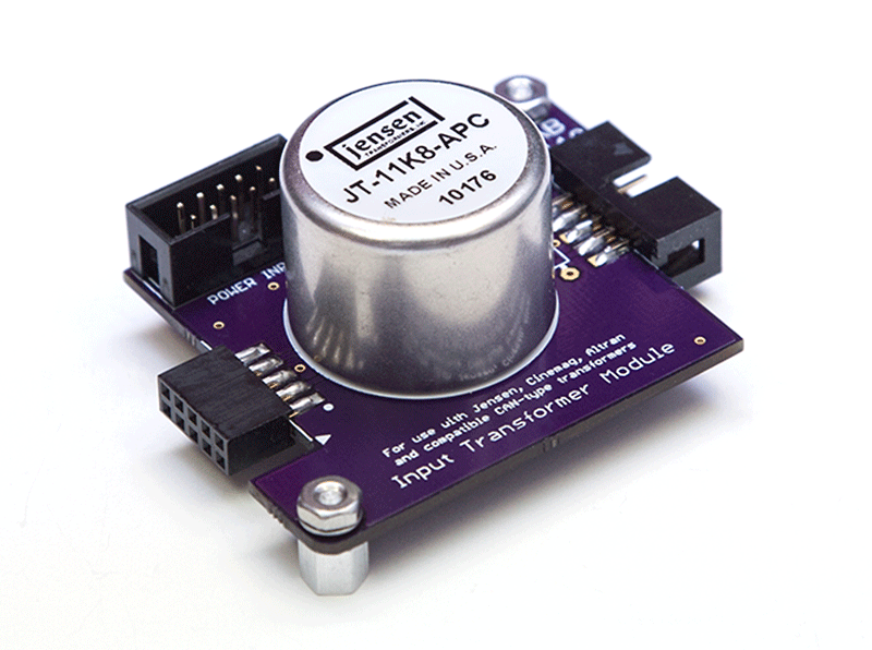
FAB2110 Input Transformer Module
We also got to see our first “mating session!” When we hooked up the FAB2010 and FAB2110 together. This is the first-time I’ve seen my module concept in reality and this got me excited about the future possibilities.
Will try to get one new FAB board designed this week.