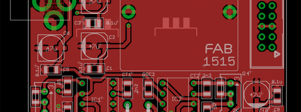
I got my prototype boards for my FAB1515 (Rev.A) Power Supply Module. I built a prototype so I can finally evaluate and test it. I know the V+ section and V- section works independently on the breadboard. But this PCB design combines the V+ and V- section (and also adds a 48V section) and I’m not sure how all of these DC/DC converters will interact with one another (since they will be all powered from the same 12V DC source).
After building the prototype, I hooked it up to my DIY Electronic Load, oscilloscope, and (2) bench meters. One of the bench meter monitors the Voltage output, and the other one monitors the current load. The oscilloscope monitors the DC output and ripple, and the Electronic Load allows me to vary the current draw from a few milliamps to hundreds of milliamps.
Right away, I noticed some problem… the V+ section voltage reading was jumping all over (15.1xx to 15.2xx and higher ) and wouldn’t show a steady number on my voltmeter. Based on experience, I know the cause of this is a too high ripple voltage. Looking at the oscilloscope confirmed my fears… the ripple voltage was very high… too high… approaching 500mV. This is CRAP! The V- section was also exhibiting high ripple voltage, though not as high as the V+ section… but still, it was high, around 300mV.


