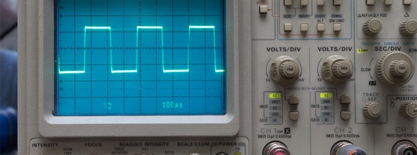
For testing audio, square waves are typically used because they can reveal a lot about the system’s response with just a quick visual analysis. What’s so special about square waves? Why not use a typical “Sine Wave” or “Triangular Wave” for testing instead?
The reason is (if you remember your calculus class), the “ideal” Square Waves are composed of an infinite summation of sine waves of different frequencies. It has a single sine wave fundamental frequency, and all it’s odd harmonics. The amplitude of each odd harmonic is 1/n. Represented by this equation: (credits: Wikipedia)
So we’re not just looking at our system’s response from a single frequency, but it’s response to the summation of different (i.e. the fundamental and all it’s odd harmonics) sine wave frequencies. Okay… so let’s continue…
For our FAB2110 Modules, you need to load your Input Transformer’s secondary with a proper resistor value. Otherwise, you may suffer from “ringing.” What is “ringing?”
Here’s a photo of “ringing” on a Square Wave signal. The transformer installed in this particular FAB2110 module is a Jensen JT-11K8APC. BTW, you’re free to use whatever Input Transformer you want. But the subject of “loading” still applies.
Ideally, we want to remove that “ringing”… because, we don’t want that. An ideal square wave does not have ringing.
How can we remove it? We can simply remove “ringing” by loading our Input Transformer with a resistor. What’s the “proper” value for loading your Input Transformer? You can do either of the following:
1. Consult the datasheet for your Input Transformer and see if there’s any specific recommendation.
2. Use an oscilloscope and try different value resistors and monitor any “ringing.”
3. Use your ears and see which one you prefer. (After all, it’s YOUR circuit/preamp/module!)
In this particular example, we’re using a Jensen JT-11K8APC. Per datasheet, we see the following:
It looks like they’re using a 15K Resistor across the transformer secondary windings (See Typical Application, Test Circuit 1, Test Circuit 2). So let’s try that…. Let’s just wedge the 15K resistor into the pad hole openings for now.
Checking the square wave output, we see this:
Look at that! The “ringing” has disappeared, and instead we’re presented with a nice square wave. Notice the edges are sharp and clean, I bet you can cut a steak with this edge! 🙂
What happens if we use a smaller value than 15K? Let’s try a 10K resistor.
It still looks good… but notice how the leading edge of the square wave is a little bit rounded… but not too much. You’ll also notice the overall Peak-to-Peak has been reduced a little bit.
Let’s try an even lower value for the Loading Resistor. Let’s try a 6K8 resistor this time. This is about less than half the original value of 15K.
Now look at that… the leading edges are even more rounder. The sharpness of that edge has definitely been softened. The overall peak-to-peak voltage is also a bit lower vs. the 10K load resistor, vs. the 15K load resistor.
What’s going on here?
What’s basically happening here is there is a High Frequency Roll Off, and this is what’s causing the rounded leading edge as seen on our square waves. If you continue loading your Input Transformer with lower and lower resistor values, you’ll soften that leading edge more and morer, which means the high-frequency response of your system will be attenuated more and more. Now, is this a bad thing? Maybe yes, maybe not. If you’re after signal integrity and flat response, you don’t want to take away frequencies from your original signal. But perhaps, you want to tame those high frequencies, and want a more beefy signal without too much harshness. Then you’d want a fairly soft leading edge. How soft is too much? Well…. it’s your system, so feel free to play with the different resistor values and see which sound you personally prefer! Happy Fabbing!


