The DC/DC Converter part I’m planning to use with my FAB1215 module is out of stock, and even if it comes back in stock, the supply quantity is so low… Mouser doesn’t keep a big inventory of this part because they said demand is low. Soooo, I can’t depend on this part being available for my customers, so I decided to roll my own DC/DC converter for +/-15V output.
Making the 12VDC to +15V output was easy, and initial breadboard testing showed it can deliver up to 370mA and more (up to 500mA). But making the 12V to -15V Inverter was a bit more problematic. The best I can squeeze out of it is -150mA, and only at 58% efficiency. The good news is I think that should be enough for 1 or 2 channels for a V- rail. The V+ rail will need to power additional LEDs and Relays so I want the V+ to have a higher current rating anyway. So I think we’re good.
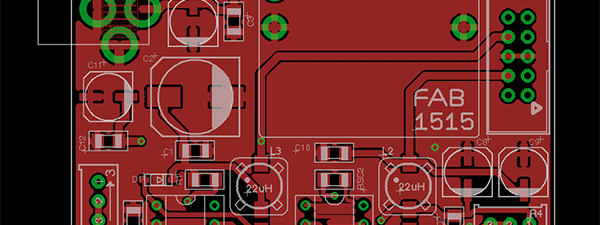
Here’s a screenshot of the proto board, now it’s time to send it to PCB fabricators and have a real prototype board made.
This design features adjustable trimmers so you can adjust the output voltages exactly to what you want. There is also an additional LC filter at the output to further reduce ripple. Heatsinks are required for the PDIP chips to deliver their maximum output current, I plan on using adhesive-backed heatsinks or glue/epoxy the aluminum heatsink to the chip body. Passive cooling (i.e. without fan) will be enough for these light-medium loads.


