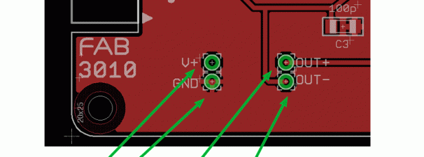
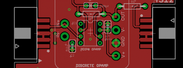
I added extra pads on the PCB so you can have easy access to the V+,GND,OUT+,OUT- signal lines on the board. This is useful if you’ll be using our FAB2010 XLR Input Module, and FAB3010 XLR Output Module in your own project and you just want to solder your voltage and control wires directly to the board (without using the Ribbon connector or a breakout board).
Build your own Preamp – FABModules – FiveFish Audio Building Blocks for DIY Projects Blog Articles
Sample FAB Setup – Power supply and other stuff
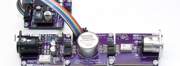
Here are some photos showing the FAB1215 Power Supply Module powering some FAB modules via a ribbon cable.
Passing your Audio Signal through an Input Transformer
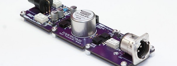
Here’s one of the simplest way to use our FABModules…. Hook up the following FABs together:
FAB2010 – XLR Input Module
FAB2110 – Input Transformer Module
FAB3010 – XLR Output Module
All that’s missing is Power, if you want to enable the -20dB Pad, Phantom Power and Polarity Reverse functions. Otherwise, it will still work without power applied. After all, it’s just an input transformer inserted in your signal chain.
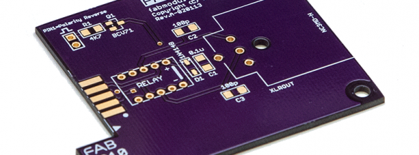
FAB3010 – XLR Output Module Prototype PCB
Received our FAB3010 XLR Output Module. Just to recap, the FAB3010 Module includes a relay-controlled Polarity Reverse. All you need to do is apply Logic “1” to the header pins (located on upper left corner) and it will switch the relays on/off. A Logic “1” can be anywhere from +3.3V to +5V, or up to your V+ voltage.
I need to make a Revision B board because I want to move the XLR jack farther out, so it won’t have any problems with clearances if you want to mount the XLR jack on a .125″ thick case panel. But other than that, I think it looks good.
Will try to populate this board in the next day or so, so I can test the Polarity Reverse logic control. I don’t foresee any problems, but the proof is in the pudding as they say.
FAB4312 – Non-Inverting Amplifier Module
The FAB4312 is a standard Non-Inverting Amplifier using OpAmps, accommodating both the PDIP8 IC format, and the API 2520-footprint Discrete OpAmp format.
If you’ll be installing a Discrete OpAmp, MillMax sockets are required to be installed on the board. An external connection, RGAIN, is required to control the gain of this amplifier. One typically uses a 10K or 22K Reverse Log Potentiometer for RGAIN in this circuit configuration.
Feel free to change the values of RF, RGAIN and R3 to suit your purpose. The formula for Voltage Gain for the amplifier is conveniently printed on the FAB Module.
For CF, we’re using a 100pf C0G NPO ceramic capacitor. You may have to adjust this capacitor value to suit the OpAmp you’ll be using in case you encounter instability or oscillations.
In addition, a trimmer resistor (R2) is provided to let you adjust DC Offset Voltage as close as possible to 0 Volts. By adjusting the DC offset to as little as possible, you reduce clicking noise when changing gain settings. This may not be an issue if you’ll be using a potentiometer for RGAIN, but if you’ll be using a selector switch to vary the value of RGAIN, then you’d want your DC offset as small as possible.

