FAB Modules

all about our FAB Modules

DOA-17 Discrete OpAmp

0 Comments
FAB Modules, FAB4000 Amplifier Modules
Tags: , ,
Posted by: admin

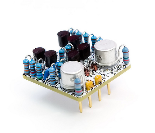
The DOA-17 is our modern remake of a vintage discrete op amp design, using modern low-noise components and improved layout. It uses the standard discrete opamp 2520/990 footprint… a roughly 1”x1” device with (6) pins, a format commonly found and used in pro-audio gear.

Running at +/-18Volts supply voltage, the DOA-12 is capable of reaching +23dBu output (loaded with a 600:600 output transformer). If one uses the DOA-17 to drive an output transformer wired for 1:2, it is possible to create high-performance preamplifiers capable of reaching +29dBu output!

Each DOA-17 is designed and tested to be stable, and oscillation-free even at maximum output levels and gain settings due to careful selection of components, efficient PCB layout, design, and construction.

Continue Reading…

FAB9010 – Output Breakout Board

0 Comments
FAB Modules, FAB9000 Utility Modules
Tags: , ,
Posted by: admin

Some people using our FAB Modules in their own DIY project may not want to use a ribbon cable for hookups. This is understandable as the usual wiring connections found in DIY boards are via solder pads.

So what we have here is our FAB9010 – Output Breakout Board.  All connections on the FAB edge connectors are “fanned out” into their own individual solder pads, and clearly labeled on the Module for ease of wiring.

Continue Reading…

FAB3010 – XLR Output Module Prototype PCB

0 Comments
FAB Modules, FAB3000 Output Modules
Tags: , , ,
Posted by: admin

Received our FAB3010 XLR Output Module.  Just to recap, the FAB3010 Module includes a relay-controlled Polarity Reverse. All you need to do is apply Logic “1” to the header pins (located on upper left corner) and it will switch the relays on/off.  A Logic “1” can be anywhere from +3.3V to +5V, or up to your V+ voltage.

I need to make a Revision B board because I want to move the XLR jack farther out, so it won’t have any problems with clearances if you want to mount the XLR jack on a .125″ thick case panel.  But other than that, I think it looks good.

Will try to populate this board in the next day or so, so I can test the Polarity Reverse logic control. I don’t foresee any problems, but the proof is in the pudding as they say.

Continue Reading…

FAB2010 XLR Input Module Prototype Testing

The moment of truth… powered up our FAB2010 XLR Input Module for testing. I’m happy to say it works great.  The Logic Control Inputs for the 20dB Pad and Phantom Power works as expected.

So basically, if you want to enable PAD or PHANTOM POWER, all you need to do is apply a small voltage to it’s respected logic pins on the board. See photo below.  A logic level control voltage can be anywhere from +3.3V to 5V up to your V+ level.  These can be switched from hard-wired switches (latching type push-buttons), or from a microprocessor or logic gate chips (TTL or CMOS type).

How it works

Continue Reading…

XLR Input + Input Transformer Module Combo

Here’s a photo of how the FAB2010 XLR Input Module and FAB2110 Input Transformer Module connect to each other.

I added a 2-pin header on the FAB2010 XLR Input Module. Later, I’ll show you how to connect those pins to your switches to control -20dB Pad and switching of Phantom Power.  I’ll also show you how to connect these pins to a Microprocessor, like an Arduino (AVR) and show it’s logic level capabilities.

Continue Reading…