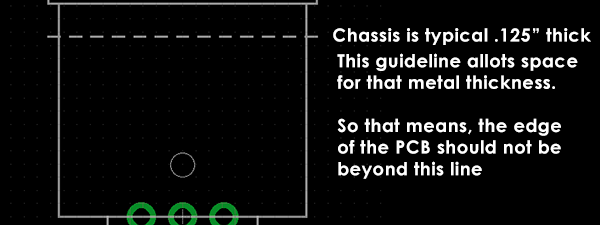
I’m working on my FAB2010 XLR Input Module and getting ready to populate it. So far, I’ve noticed already a problem with the XLR jack…. it’s off by a few millimeters positioned on the board.
That’s the problem… I trusted the Eagle library for the XLR jack to be 100% correct. It’s not.
When I got the actual XLR part, that’s when I discovered the problem. So to avoid this problem again in the future, I edited the library and made the corrections. The XLR jack will be bolted into the case, so I also had to consider the metal case thickness. In this case, I assigned that as 0.125″. Depending on your chosen case, yours may be thinner, or thicker. So make sure to adjust for that.
After modifying the library part, and moving it’s location on the PCB, make sure to perform a DRC or visually check if there are any overlapping traces, or traces going over drilled holes. It’s also a good idea to double-check the pin assignments (gnd=1, hot=2, cold=3) on your XLR part.

Take note, you also want to be able to bolt the XLR cover, without hitting your PC Board’s edges. So I’m going route a U-shaped cutout where the XLR sits to avoid that potential problem. (It’s probably overkill, but I’d rather be sure than send out another PCB for prototyping again. That costs money.)
Here’s the new FAB2010 XLR Input Module, Rev.B.


